Tech Articles

Caster vs Camber: What's the Difference? Caster and camber are lesser known terms even for...
MAPerformance 2022 WRX Catback A sneak peak at the up-coming MAPerformance 2022 WRX Catback As...
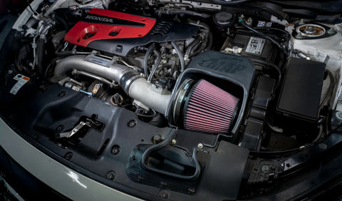
FREE SHIPPING ON ALL DOMESTIC ORDERS $199+ Re-Designing the MAPerformance FK8 Intake Posted by Kevin...
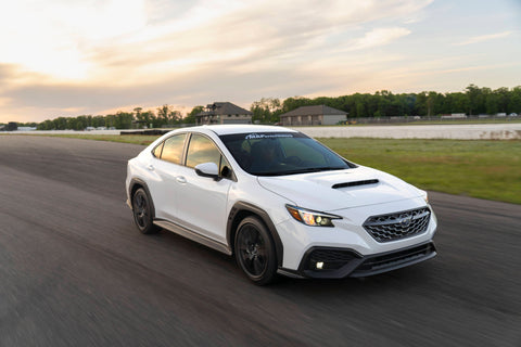
Engineering Our22' WRX Intake Posted by Kevin Boeselager, 6 July 2022 Florida man builds family...
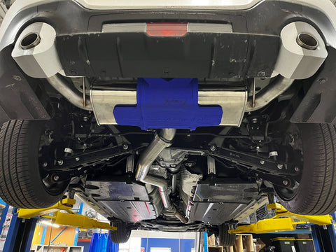
FREE SHIPPING ON ALL DOMESTIC ORDERS $149+ MAPerformance 22' BRZ Catback Development Posted by Kevin...
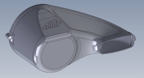
WHAT GOES INTO MAKING A MAP PRODUCT? Designing our BRZ Intake Posted by Kevin Boeselager,...
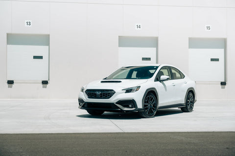
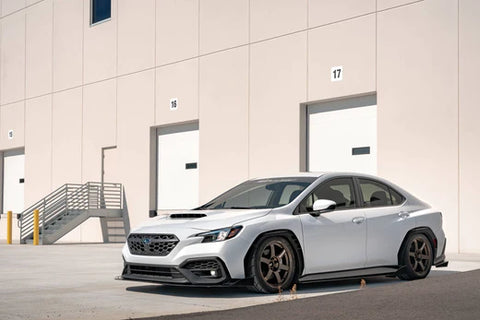
FREE SHIPPING ON ALL DOMESTIC ORDERS $199+ The All New 2022 WRX Posted by Kevin...
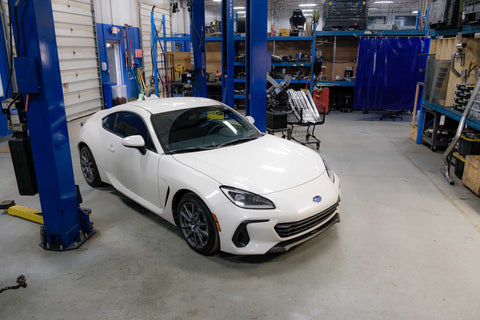
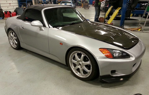
MAPerformance's BRZ Build Thread Pt. 1 Posted by Kevin Boeselager, 2 June 2022 From Dealership...